1.1 India’s Intended Nationally Determined Contributions (INDCs) aim to reduce the emissions intensity of its gross domestic product (GDP) by 33 to 35 percent by 2030 from 2005 level. Any effort to achieve this target is contingent upon the increase in efficiency of energy use across all sectors, especially in the building sector. The building sector in India consumes over 30% of the total electricity consumed in the country annually and is second only to the industrial sector as the largest emitter of greenhouse gases (GHGs).
1.2 Out of the total electricity consumed in the building sector, about 75% is used in residential buildings. The gross electricity consumption in residential buildings has been rising sharply over the years. For instance, the consumption figure rose to about 260 TWH in 2016-17 from about 55 TWH in 1996-97. That is an increase by more than four times in 20 years. Projections show it rising to anywhere between 630 and 940 tWh by 2032. Among various reasons, increased use of decentralized room-based air-conditioning units in homes for thermal comfort is an important reason contributing to this rapid increase in the electricity use in residential buildings. The demand for air-conditioning will continue its exponential growth with improvement in household incomes and will become the dominant contributor of GHG emissions nation-wide owing to increased electricity consumption. This situation calls for an immediate energy conservation action plan.
1.3 Energy codes for new buildings are an important regulatory measure for ushering energy efficiency in the building sector. They are particularly relevant for countries like India where the building stock is growing rapidly. The commercial sector among buildings has been addressed by the Energy Conservation Building Code (ECBC) for Commercial Buildings. Given the current and anticipated rapid growth in the resi-dential building stock across India and the consequent opportunities as well as the necessity for energy conservation in this sector, the Energy Conservation Code for residential Buildings is established by the Ministry of Power.
1.4 Building envelope consists of walls, roof, and fenestration (openings including windows, doors, vents, etc.). Design of building envelope influences heat gain/loss, natural ventilation, and daylighting, which, in turn, determines indoor tempera-tures, thermal comfort, and sensible cooling/heating demand.
1.5 Most parts of India have cooling-dominated climates. Consideration of heat gain is often not given sufficient importance during residential building design. It is seen that current practices of residential building design and construction show a large variation in heat gains and hence in the sensible cooling demand. Depending on the envelope design and construction adopted for residential buildings located in a particular climate zone, the minimum and maximum sensible cooling demand can vary by as much as 1:3.
1.6 Energy Conservation Building Code – Residential (ECBC-R) (Part I: Building Enve-lope) has been prepared to set minimum building envelope performance stan-dards to limit heat gains (for cooling dominated climates) and to limit heat loss (for heating dominated climates), as well as for ensuring adequate natural ventilation and daylighting potential. the code provides design flexibility to innovate and vary important envelope components such as wall type, window size, type of glazing, and external shading to windows to meet the compliance.
1.7 The code is applicable to all residential buildings and residential parts of ‘mixed land-use projects’, both built on a plot area of ≥500 m2. However, states and municipal bodies may reduce the plot area based on the prevalence in their area of jurisdiction. This provision is kept to take into account the prevalent plot sizes and housing types in different states, enabling the inclusion of a greater percentage of new multi-dwelling unit residential buildings within the scope of this code. (Please refer paragraph 2.4.)
1.8 Building envelope has the highest impact on thermal comfort, and consequently on the energy use in residential buildings. The envelope is also a permanent compo-nent of the building with the longest life cycle. An early introduction of this code would improve the design and construction of new residential building stock being built currently and in the near future, thus significantly curtailing the anticipated energy demand for comfort cooling in times to come. This critical investment in envelope design and construction made today will reap benefits of reduced GHG emissions for the lifetime of the buildings.
1.9 Part I – Building Envelope of ECBC-R is designed in a simple-to-apply format, requiring only simple calculations based on inputs from the architectural design drawings of buildings. This can be used by architects and engineers and will not require any simulation software. This also enables the code to be readily adopted in the building bye-laws. A compliance tool is also available on BEE website to aid in the calculations and compliance check.
1.10 Part I – Building Envelope is the first part of ECBC-R. It is envisaged that new parts will be added to address other aspects, such as energy efficiency in electro-mechanical equipment for building operation, renewable energy generation, and embodied energy of building materials and structural systems.
2.1 The code sets minimum performance standards for building envelope to limit heat gains (for cooling dominated climates) and limit heat loss (for heating dominated climates) through it. The code gives the following provisions to this effect:
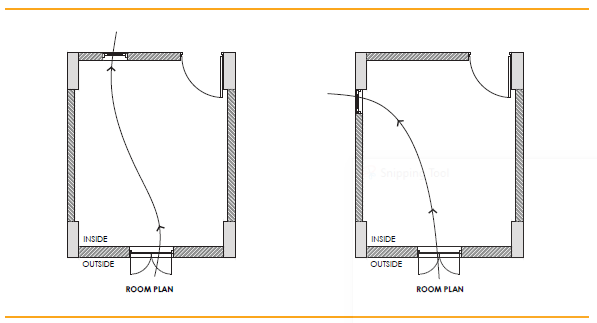
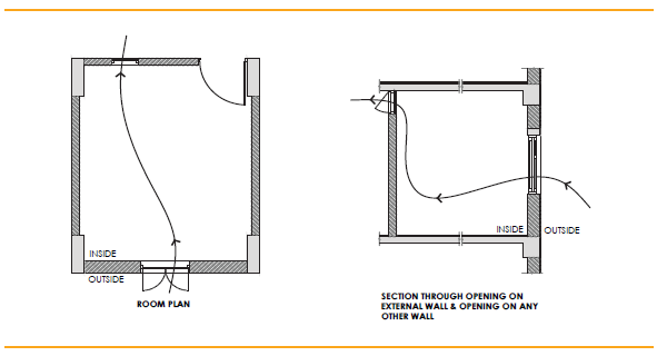
2.2 The code sets minimum building envelope performance standard for adequate natural ventilation potential by specifying minimum openable window-to-floor area ratio (WFRop)
2.3 The code sets minimum building envelope performance standard for adequate daylight potential by specifying minimum visible light transmittance (VLT) for the non-opaque building envelope components.
2.4 The code applies to (a) ‘Residential buildings’ built on a plot area ≥500 m2 and (b) Residential part of ‘Mixed land-use building projects’, built on a plot area of ≥500 m2.
‘Residential building’ includes any building in which sleeping accommodation is provided for normal residential purposes with or without cooking or dining or both facil-ities. this definition includes:
The following are excluded from the definition of ‘residential building’ for the purpose of this code.
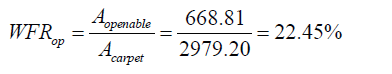
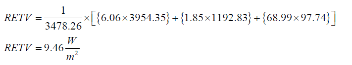
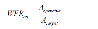
3.1.1 Openable window-to-floor area ratio (WFRop) indicates the potential of using external air for ventilation. Ensuring minimum WFRop helps in ventilation, improvement in thermal comfort, and reduction in cooling energy.
3.1.2 The openable window-to-floor area ratio (WFRop) is the ratio of openable area to the carpet area of dwelling units.
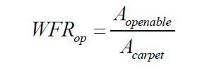
WFRop: openable window-to-floor area ratio
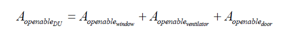
Aopenable: openable area (m2); it includes the openable area of all windows and ventilators, opening directly to the external air, an open alcony,‘verandah’, corridor or shaft; and the openable area of the doorsopening directly into an open balcony.
Exclusions: All doors opening into corridors. External doors on ground floor, for example, ground-floor entrance doors or back-yard doors.
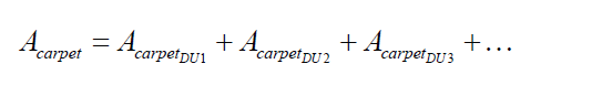
Acarpet: carpet area of dwelling units (m2); it is the net usable floor area of a dwelling unit, excluding the area covered by the external walls, areas under services shafts, exclusive balcony or verandah area and exclusive open terrace area, but includes the area covered by the internal partition walls of the dwelling unit.
3.1.3 The openable window-to-floor area ratio (WFRop) shall not be less than the values given in table 1.
| Climatic zone | Minimum WFRop (%) |
|---|---|
| Composite | 12.50 |
| Hot-Dry | 10.00 |
| Warm-Humid | 16.66 |
| Temperate | 12.50 |
| Cold | 8.33 |
| SOURCE Adapted from Bureau of Indian Standards (BIS). 2016. National Building Code of India 2016.New Delhi: BIS. | |
3.2.1 Visible light transmittance (VLT) of non-opaque building envelope components (transparent/translucent panels in windows, doors, ventilators, etc.), indicates the potential of using daylight. Ensuring minimum VLT helps in improving daylighting, thereby reducing the energy required for artificial lighting.
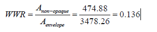
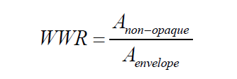
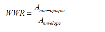
3.2.2 The glass used in non-opaque building envelope components (transparent/trans-lucent panels in windows, doors, etc.) shall comply with the requirements given in table 2. The VLt requirement is applicable as per the window-to-wall ratio (WWR) of the building. WWR is the ratio of the area of non-opaque building envelope compo-nents of dwelling units to the envelope area (excluding roof) of dwelling units
| Window-to-wall ratio (WWR) | Minimum VLT |
|---|---|
| 0-0.30 | 0.27 |
| 0.31-0.40 | 0.20 |
| 0.41-0.50 | 0.16 |
| 0.51-0.60 | 0.13 |
| 0.61-0.70 | 0.11 |
| SOURCE Bureau of Indian Standards (BIS). 2016. National Building Code of India 2016. New Delhi: BIS. | |
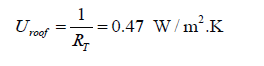
3.3.1 Thermal transmittance (Uroof) characterizes the thermal performance of the roof of a building. Limiting the Uroof helps in reducing heat gains or losses from the roof, thereby improving the thermal comfort and reducing the energy required for cooling or heating.
3.3.2 Thermal transmittance of roof shall comply with the maximum Uroof value of 1.2 W/m2.K.
3.3.3The calculation shall be carried out, using Equation 3 as shown below.
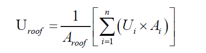
Uroof: thermal transmittance of roof (W/m2.K
Aroof: total area of roof (m2)
Ui: thermal transmittance values of different roof constructions (W/m2.K)
Ai: areas of different constructions (m2)
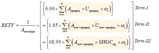
3.4.1 Residential envelope heat transmittance (RETV) is the net heat gain rate (over the cooling period) through the building envelope (excluding roof) of the dwelling units divided by the area of the building envelope (excluding roof) of the dwelling units. Its unit is W/m2.
RETV characterizes the thermal performance of the building envelope (except roof). Limiting the RETV value helps in reducing heat gains from the building envelope, thereby improving the thermal comfort and reducing the electricity required for cooling.
RETV formula takes into account the following:
3.4.2 The RETV for the building envelope (except roof) for four climate zones, namely, Composite Climate, Hot-Dry Climate, Warm-Humid Climate, and Temperate Climate, shall comply with the maximum RETV of 15 W/m2.
3.4.3 The RETV calculation of the building envelope (except roof) shall be carried out, using Equation 4 as shown below.
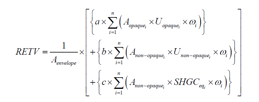
Aenvelope: envelope area (excluding roof) of dwelling units (m2). It is the gross external wall area (includes the area of the walls and the openings such as windows and doors).
Aopaquei: areas of different opaque building envelope components (m2)
Uopaquei: thermal transmittance values of different opaque building envelope components (W/m2.K)
Anon-opaquei: areas of different non-opaque building envelope components (m2)
Unon-opaquei: thermal transmittance values of different non-opaque building envelope components (W/m2.K)
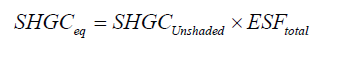
SHGCeqi: equivalent solar heat gain coefficient values of different non-opaque building envelope components (refer to Annexure 7)
ωi: orientation factor of respective opaque and non-opaque building envelope components; it is a measure of the amount of direct and diffused solar radiation that is received on the vertical surface in a specific orientation (values are given in Annexure 6)
The coefficients of RETV formula, for different climate zones (for classification, refer to Annexure 2), are given in Table 3.
| Climate zone | a | b | c |
|---|---|---|---|
| Composite | 6.06 | 1.85 | 68.99 |
| Hot-Dry | 6.06 | 1.85 | 68.99 |
| Warm-Humid | 5.15 | 1.31 | 65.21 |
| Temperate | 3.38 | 0.37 | 63.69 |
| Cold | Not applicable (Refer Section 3.5) | ||
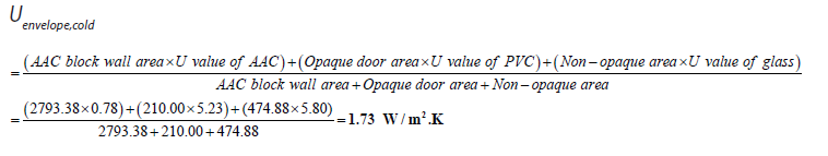
3.5.1 Thermal transmittance (Uenvelope,cold) characterizes the thermal performance of the building envelope (except roof). Limiting the Uenvelope,cold helps in reducing heat losses from the building envelope, thereby improving the thermal comfort and reducing the energy required for heating.
Uenvelope,cold takes into account the following:
3.5.2 The thermal transmittance of the building envelope (except roof) for cold climate shall comply with the maximum of 1.8 W/m2.K.
3.5.3 The calculation of the building envelope (except roof) shall be carried out, using Equation 5 as shown below.
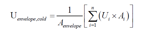
Uenvelope,cold: thermal transmittance of building envelope (except roof) for cold climate (W/mm2.K)
Aenvelope: envelope area (excluding roof) of dwelling units (m2). It is the gross external wall area (includes the area of the walls and the openings such as windows and doors)
Ui: thermal transmittance of different opaque and non-opaque building envelope components (W/m2.K)
Ai: area of different opaque and non-opaque opaque building envelope components (m2)
4.1 The code is designed in a simple-to-apply format, requiring only simple calculations based on inputs from the architectural design drawings of residential buildings. This can be used by architects and engineers and will not require any simulation software.
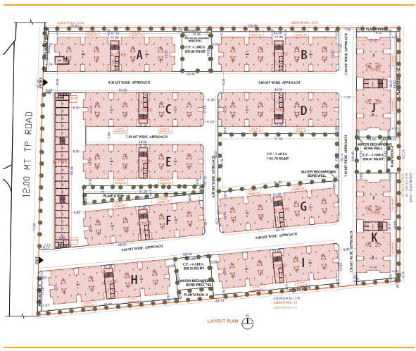
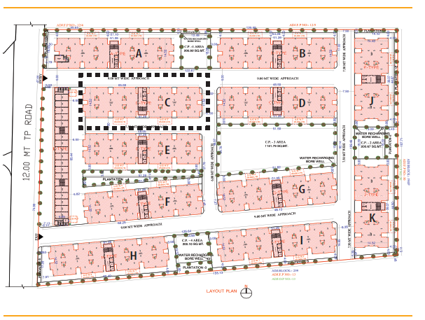
4.2 If a building project has more than one building block, each building block is required to comply with the code. However, for identical building blocks with the same orientation, the compliance has to be shown for one building block.
4.3 The steps for checking compliance for Composite Climate, Hot-Dry Climate, Warm-Humid Climate, and Temperate Climate are as follows:
Step 1: Openable window-to-floor area ratio shall comply with the minimum WFRop values as given in Table 1 of paragraph 3.1.3. For calculation of WFRop, refer Annexure 3.
Step 2: Visible light transmittance (VLT) of non-opaque building envelope components shall comply with the minimum VLT values as given in Table 2 of paragraph 3.2.2.
Step 3: Thermal transmittance of roof shall comply with the maximum Uroof value of 1. 2 W/m2.K (refer paragraph 3.3). to calculate the U values of roof, refer Annexure 5.
Step 4: Residential envelope transmittance value (RETV) for building envelope (except roof) shall comply with the maximum RETV of 15 W/m2 (refer paragraph 3.4)
An example of code compliance is given in Annexure 8 (Example 1).
4.4 The steps for checking compliance for cold climate are as follows:
Step 1: Openable window-to-floor area ratio shall comply with the minimum WFRop values as given in Table 1 of paragraph 3.1.3. For calculation of WFRop refer Annexure 3.
Step 2: Visible light transmittance (VLT) of non-opaque building envelope components shall comply with the minimum VLT values as given in Table 2 of paragraph 3.2.2.
Step 3: Thermal transmittance of roof shall comply with the maximum Uroof value of 1.2 W/m2.K (refer paragraph 3.3). To calculate the U values of roof, refer Annexure 5.
Step 4: Thermal transmittance of building envelope (except roof) for cold climate shall comply with the maximum value of 1.8 W/m2.K (refer paragraph 3.5).
An example of code compliance is given in Annexure 8 (Example 2).
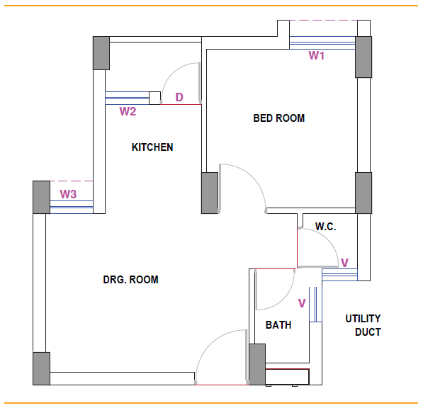
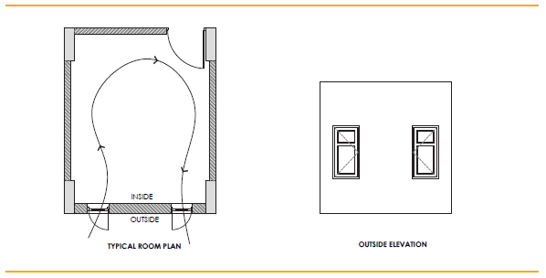
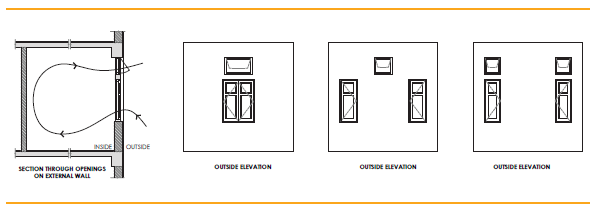
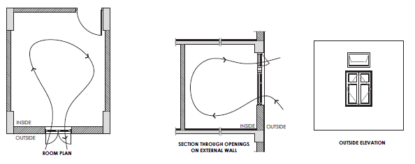
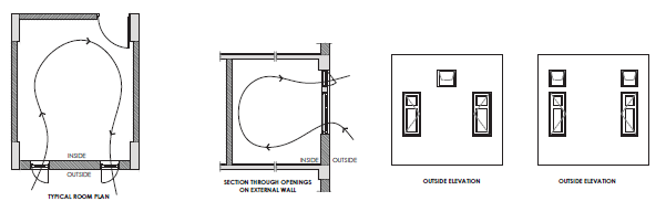
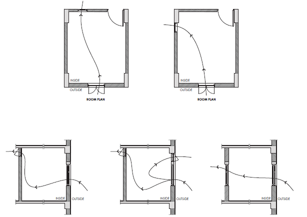
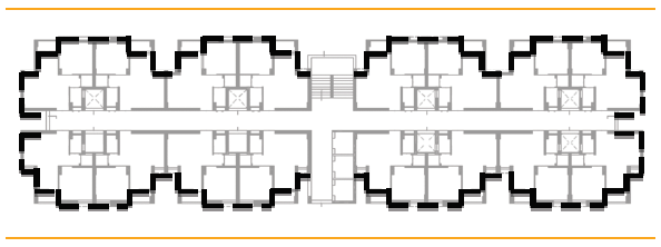
Building Envelope: The elements of a building that separate the habitable spaces of dwelling units from the exterior and are exposed to the ambient (i.e., exposed directly to external air and opening into balconies). It does not include walls facing open corridors and enclosed shafts, as well as walls of common services such as lifts and staircase. (See Figure 1. Dotted lines show the walls included in the definition of building envelope in this code.)
Carpet Area: Carpet area is the net usable floor area of a dwelling unit, excluding the area covered by the external walls, areas under services shafts, exclusive balcony or verandah area and exclusive open terrace area, but includes the area covered by the internal parti-tion walls of the dwelling unit.
Envelope Area: Envelope area (excluding roof) of dwelling units is the overall area of the building envelope (see definition ’Building Envelope’). It is the gross external wall area (includes the area of the walls and the openings such as windows and doors), with measurement taken horizontally from outside surface to outside surface and measured vertically from the top of the floor to the top of the roof.
Non-opaque Building Envelope Components: Non-opaque building envelope compo-nents include transparent/translucent panels in windows, doors, ventilators, etc.
Opaque Building Envelope Components: Opaque building envelope components include walls, opaque panels in doors, windows, ventilators, etc.
Openable Window-to-Floor Ratio (WFRop): The openable window-to-floor ratio (WFRop) is the ratio of the total openable area to the total carpet area of dwelling units. The total openable area of a dwelling unit is the addition of openable area of all windows and venti-lators, opening directly to the external air, an open balcony, ‘verandah’, corridor or shaft; and the openable area of the doors opening directly into an open balcony.
Exclusions: Doors opening into corridors and external doors on ground floor (for e.g. ground floor entrance doors or back-yard doors).
Orientation Factor (ω): It is a measure of the amount of direct and diffused solar radiation that is received on the vertical surface in a specific orientation. This factor accounts for and gives weightage to the fact that the solar radiation falling on different orientations of walls is not same.
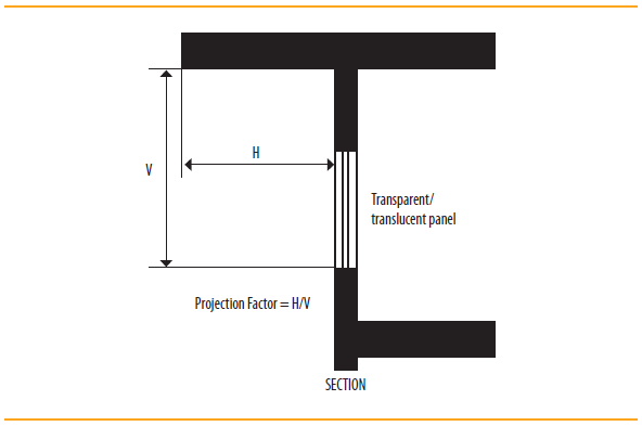
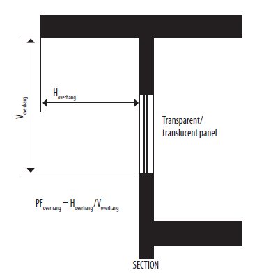
Projection Factor, Overhang: Projection factor (overhang) is the ratio of the horizontal depth of the external shading projection to the sum of the height of a non-opaque component and the distance from the top of the same component to the bottom of the farthest point of the external shading projection, in consistent units (Figure 2).
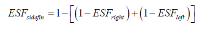
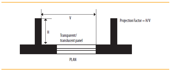
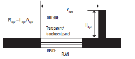
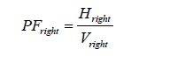
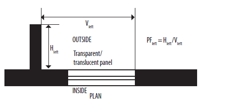
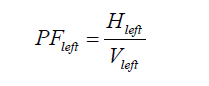
Projection Factor, Side Fin: Project factor (side fin) is the ratio of the horizontal depth of the external shading projection to the distance from a non-opaque component to the farthest point of the external shading projection, in consistent units (Figure 3).
Residential Envelope Heat Transmittance (RETV): RETV is the net heat gain rate (over the cooling period) through the building envelope of dwelling units (excluding roof) divided by the area of the building envelope (excluding roof) of dwelling units. Its unit is W/m2.
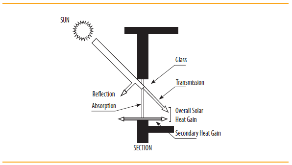
Solar Heat Gain Coefficient (SHGC): ShGC is the fraction of incident solar radiation admitted through non-opaque components, both directly transmitted, and absorbed and subsequently released inward through conduction, convection, and radiation (Figure 4).
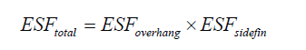
SHGC Equivalent: SHGC Equivalent is the SHGC for a non-opaque component with a permanent external shading projection. It is calculated by multiplying the External Shading Factor (ESF) with the SHGC of unshaded non-opaque component.
U Value: Thermal transmittance (U value) is the heat transmission in unit time through unit area of a material or construction and the boundary air films, induced by unit temperature difference between the environments on either side. Unit of U value is W/m2.K. The U value for a wall/roof/glazing indicates its ability to transfer heat through conduction.
Visible Light Transmittance (VLT): VLT is the ratio of the total transmitted light to the total incident light. It is a measure of the transmitted light in the visible portion of the spectrum through a material.
Window-to-Wall Ratio (WWR): WWR is the ratio of the non-opaque building envelope components area to the envelope area (excluding roof) of dwelling units.
| City | Climate Type | City | Climate Type |
|---|---|---|---|
| Ahmedabad | Hot and Dry | Kurnool | Warm and Humid |
| Allahabad | Composite | Leh | Cold |
| Amritsar | Composite | Lucknow | Composite |
| Aurangabad | Hot and Dry | Ludhiana | Composite |
| Bengaluru | Temperate | Chennai | Warm and Humid |
| Barmer | Hot and Dry | Manali | Cold |
| Belgaum | Warm and Humid | Mangaluru | Warm and Humid |
| Bhagalpur | Warm and Humid | Mumbai | Warm and Humid |
| Bhopal | Composite | Nagpur | Composite |
| Bhubaneshwar | Warm and Humid | Nellore | Warm and Humid |
| Bikaner | Hot and Dry | New Delhi | Composite |
| Chandigarh | Composite | Panjim | Warm and Humid |
| Chitradurga | Warm and Humid | Patna | Composite |
| Dehradun | Composite | Pune | Warm and Humid |
| Dibrugarh | Warm and Humid | Raipur | Composite |
| Guwahati | Warm and Humid | Rajkot | Composite |
| Gorakhpur | Composite | Ramagundam | Warm and Humid |
| Gwalior | Composite | Ranchi | Composite |
| Hissar | Composite | Ratnagiri | Warm and Humid |
| Hyderabad | Composite | Raxaul | Warm and Humid |
| Imphal | Warm and Humid | Saharanpur | Composite |
| Indore | Composite | Shillong | Cold |
| Jabalpur | Composite | Sholapur | Hot and Dry |
| Jagdelpur | Warm and Humid | Srinagar | Cold |
| Jaipur | Composite | Sundernagar | Cold |
| Jaisalmer | Hot and Dry | Surat | Hot and Dry |
| Jalandhar | Composite | Tezpur | Warm and Humid |
| Jamnagar | Warm and Humid | Tiruchirappalli | Warm and Humid |
| Jodhpur | Hot and Dry | Trivandrum | Warm and Humid |
| Jorhat | Warm and Humid | Tuticorin | Warm and Humid |
| Kochi | Warm and Humid | Udhagamandalam | Cold |
| Kolkata | Warm and Humid | Vadodara | Hot and Dry |
| Kota | Hot and Dry | Veraval | Warm and Humid |
| Kullu | Cold | Vishakhapatnam | Warm and Humid |
In case exact openable area is not known, the following default values can be used:
| Type of window/door/ventilator | Percentage openable area |
|---|---|
| Casement | 90% |
| Sliding (2 panes) | 50% |
| Sliding (3 panes) | 67% |
Add openable areas of all dwelling units to get the total openable area.

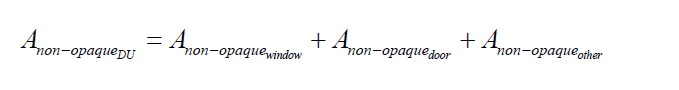
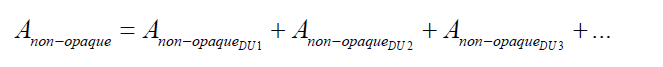
Add non-opaque areas of all dwelling units to get the total non-opaque area of the building block. Non-opaque components facing open corridors and enclosed shafts, as well as walls of common services such as lifts and staircase are to be excluded.

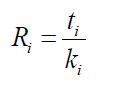
Ri is the thermal resistance of material layer i, m2.K/W
ti is the thickness of material layer i, m
ki is the thermal conductivity of material layer i, W/(m.K)
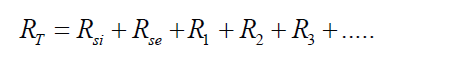
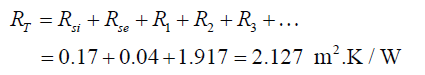
RT is the total thermal resistance, m2.K/W
Rsi is the interior surface film thermal resistance, m2.K/W
Rse is the exterior surface film thermal resistance, m2.K/W
R1 is the thermal resistance of material layer 1, m2.K/W
R2 is the thermal resistance of material layer 2, m2.K/W
R3 is the thermal resistance of material layer 3, m2.K/W
Use these default values for calculation,
| Wall | Roof | ||
|---|---|---|---|
| All Climatic Zones | Composite Climate, Hot-Dry Climate, Warm-Humid Climate, and Temperate Climate | Cold Climate | |
| Rsi (m2.K/W) | 0.13 | 0.17 | 0.10 |
| Rse (m2.K/W) | 0.04 | 0.04 | 0.04 |
| SOURCE Adapted from Bureau of Energy Efficiency (BEE), 2009. Energy Conservation Building Code User Guide, New Delhi | |||
The thermal conductivity of commonly used building materials is given in Table 7, which can be used to calculate the thermal resistance (R value).
U is the overall heat transfer coefficient, W/m2.K
Table 7 gives typical thermal properties of commonly used building and insulating mate-rials. this is not an all-inclusive list. In case, thermal conductivity values, measured using the appropriate IS codes, are available; those can also be used for calculations.
| S.No | Type of material | Density (kg/m3) | Thermal Conductivity (W/m.K) | Specific heat capacity (kJ/kg.K) | Source |
|---|---|---|---|---|---|
| I | Building materials | ||||
| 1 | Solid burnt clay brick | 1920 | 0.980 | 0.80 | (1) |
| 2 | Solid burnt clay brick | 1760 | 0.850 | NA | (1) |
| 3 | Solid burnt clay brick | 1600 | 0.740 | NA | (1) |
| 4 | Solid burnt clay brick | 1440 | 0.620 | NA | (1) |
| 5 | Resource efficient (hollow) brick | 1520 | 0.631 | 0.65 | (4) |
| 6 | Fly ash brick | 1650 | 0.856 | 0.93 | (2) |
| 7 | Solid concrete block 25/50 | 2427 | 1.396 | 0.20 | (4) |
| 8 | Solid concrete block 30/60 | 2349 | 1.411 | 0.30 | (4) |
| 9 | Aerated autoclaved concrete (AAC) block | 642 | 0.184 | 1.24 | (4) |
| 10 | Cement stabilized soil block (CSEB) | 1700 | 1.026 | 1.03 | (5) |
| 11 | Cement stabilized soil block (CSEB) | 1800 | 1.201 | 1.07 | (5) |
| 12 | Cement stabilized soil block (CSEB) | 1900 | 1.303 | 1.07 | (5) |
| 13 | Dense concrete | 2410 | 1.740 | 0.88 | (3) |
| 14 | Reinforced concrete cement (RCC) | 2288 | 1.580 | 0.88 | (3) |
| 15 | Brick tile | 1892 | 0.798 | 0.88 | (3) |
| 16 | Lime concrete | 1646 | 0.730 | 0.88 | (3) |
| 17 | Mud Phuska | 1622 | 0.519 | 0.88 | (3) |
| 18 | Cement mortar | 1648 | 0.719 | 0.92 | (3) |
| 19 | Cement plaster | 1762 | 0.721 | 0.84 | (3) |
| 20 | Gypsum plaster | 1120 | 0.512 | 0.96 | (3) |
| 21 | Cellular concrete | 704 | 0.188 | 1.05 | (3) |
| 22 | AC sheet | 1520 | 0.245 | 0.84 | (3) |
| 23 | Gl sheet | 7520 | 61.060 | 0.50 | (3) |
| 24 | Timber | 480 | 0.072 | 1.68 | (3) |
| 25 | Timber | 720 | 0.144 | 1.68 | (3) |
| 26 | Plywood | 640 | 0.174 | 1.76 | (3) |
| 27 | Glass | 2350 | 0.814 | 0.88 | (3) |
| 28 | Tar felt (2.3 kg/m2) | 0.479 | 0.88 | (3) | |
| II | Insulating materials | ||||
| 1 | Expanded polystyrene | 16.0 | 0.038 | 1.34 | (3) |
| 2 | Expanded polystyrene | 24.0 | 0.035 | 1.34 | (3) |
| 3 | Expanded polystyrene | 34.0 | 0.035 | 1.34 | (3) |
| 4 | Foam glass | 127.0 | 0.056 | 0.75 | (3) |
| 5 | Foam glass | 160.0 | 0.055 | 0.75 | (3) |
| 6 | Foam concrete | 320.0 | 0.070 | 0.92 | (3) |
| 7 | Foam concrete | 400 | 0.084 | 0.92 | (3) |
| 8 | Foam concrete | 704.0 | 0.149 | 0.92 | (3) |
| 9 | Cork slab | 164.0 | 0.043 | 0.96 | (3) |
| 10 | Cork slab | 192.0 | 0.044 | 0.96 | (3) |
| 11 | Cork Slab | 304.0 | 0.055 | 0.96 | (3) |
| 12 | Rock wool (unbonded) | 92.0 | 0.047 | 0.84 | (3) |
| 13 | Rock wool (unbonded) | 150.0 | 0.043 | 0.84 | (3) |
| 14 | Mineral wool (unbonded) | 73.5 | 0.030 | 0.92 | (3) |
| 15 | Glass wool (unbonded) | 69.0 | 0.043 | 0.92 | (3) |
| 16 | Glass wool (unbonded) | 189.0 | 0.040 | 0.92 | (3) |
| 17 | Resin bonded mineral wool | 48.0 | 0.042 | 1.00 | (3) |
| 18 | Resin bonded mineral wool | 64.0 | 0.038 | 1.00 | (3) |
| 19 | Resin bonded mineral wool | 99.0 | 0.036 | 1.00 | (3) |
| 20 | Resin bonded mineral wool | 16.0 | 0.040 | 1.00 | (3) |
| 21 | Resin bonded mineral wool | 24.0 | 0.036 | 1.00 | (3) |
| 22 | Exfoliated vermiculite (loose) | 264.0 | 0.069 | 0.88 | (3) |
| 23 | Asbestos mill board | 1397.0 | 0.249 | 0.84 | (3) |
| 24 | Hard board | 979.0 | 0.279 | 1.42 | (3) |
| 25 | Straw board | 310.0 | 0.057 | 1.30 | (3) |
| 26 | Soft board | 320.0 | 0.066 | 1.30 | (3) |
| 27 | Soft board | 249.0 | 0.047 | 1.30 | (3) |
| 28 | Wall board | 262.0 | 0.047 | 1.26 | (3) |
| 29 | Chip board | 432.0 | 0.067 | 1.26 | (3) |
| 30 | Chip board (perforated) | 352.0 | 0.066 | 1.26 | (3) |
| 31 | Particle board | 750.0 | 0.098 | 1.30 | (3) |
| 32 | Coconut pith insulation board | 520.0 | 0.060 | 1.09 | (3) |
| 33 | Jute fibre | 329.0 | 0.067 | 1.09 | (3) |
| 34 | Wood wool board (bonded with cement) | 398.0 | 0.081 | 1.13 | (3) |
| 35 | Wood wool board (bonded with cement) | 674.0 | 0.108 | 1.13 | (3) |
| 36 | Coir board | 97.0 | 0.038 | 1.00 | (3) |
| 37 | Saw dust | 188.0 | 0.051 | 1.00 | (3) |
| 38 | Rice husk | 120.0 | 0.051 | 1.00 | (3) |
| 39 | Jute felt | 291.0 | 0.042 | 0.88 | (3) |
| 40 | Closed cell flexible elastomeric foam - NBR | 40-55 | 0.043 | 1.20 | (3) |
|
NA: Not Applicable |
|||||
In case, the construction has air layer, use values of thermal resistance of air layer given in Table 8 for U value calculation.
| Thickness of Air Layer (mm) | Thermal resistance (m2.K/W) | ||
|---|---|---|---|
| Wall in All Climatic Zones | Roof in composite climate, Hot and Dry climate, Warm and Humid climate, and temperate climate | Roof in cold climate | |
| 5 | 0.12 | 0.10 | 0.10 |
| 7 | 0.12 | 0.12 | 0.12 |
| 10 | 0.14 | 0.14 | 0.14 |
| 15 | 0.16 | 0.16 | 0.16 |
| 25 | 0.18 | 0.18 | 0.17 |
| 50 | 0.18 | 0.20 | 0.17 |
| 100 | 0.18 | 0.20 | 0.17 |
| 300 | 0.18 | 0.21 | 0.17 |
| SOURCE Adapted from Bureau of Energy Efficiency (BEE), 2009. Energy Conservation Building Code User Guide, New Delhi | |||
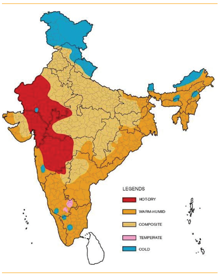
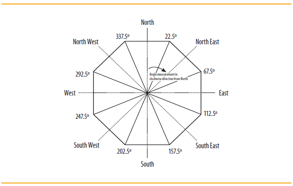
The orientation factor (ω) is a measure of the amount of direct and diffused solar radiation that is received on the vertical surface in a specific orientation. This factor accounts for and gives weightage to the fact that the solar radiation falling on different orientations of walls is not same. It has been defined for the latitudes ≥23.5 ̊N and latitudes 23.5 ̊N (Table 9). Table 9 should be read in conjunction with Figure 6.
| Orientation | Orientation factor (ω) | |
|---|---|---|
| Latitudes ≥23.5˚N | Latitudes <23.5˚N | |
| North (337.6˚–22.5˚) | 0.550 | 0.659 |
| North-east (22.6˚–67.5˚) | 0.829 | 0.906 |
| East (67.6˚–112.5˚) | 1.155 | 1.155 |
| South-east (112.6˚–157.5˚) | 1.211 | 1.125 |
| South (157.6˚–202.5˚) | 1.089 | 0.966 |
| South-west (202.6˚–247.5˚) | 1.202 | 1.124 |
| West (247.6˚–292.5˚) | 1.143 | 1.156 |
| North-west (292.6˚–337.5˚) | 0.821 | 0.908 |
SHGC Equivalent is the SHGC for a non-opaque component with a permanent external shading projection (overhang and side fins). It is calculated by multiplying the External Shading Factor (ESF) with the SHGC of unshaded non-opaque component. ESF values are defined based on the projection factor (PF). The procedure for calculation is given below:

| External Shading Factor for Overhang (ESFoverhang) for LAT ≥ 23.5˚N | ||||||||
|---|---|---|---|---|---|---|---|---|
| Orientation | North | North-east | East | South-East | South | South-west | West | North-west |
| PFoverhang | (337.6˚–22.5˚) | (22.6˚–67.5˚) | (67.6˚–112.5˚) | (112.6˚–157.5˚) | (157.6˚–202.5˚) | (202.6˚–247.5˚) | (247.6˚–292.5˚) | (292.6˚–337.5˚) |
| <0.10 | 1.000 | 1.000 | 1.000 | 1.000 | 1.000 | 1.000 | 1.000 | 1.000 |
| 0.10-0.19 | 0.955 | 0.930 | 0.922 | 0.906 | 0.881 | 0.905 | 0.922 | 0.930 |
| 0.20-0.29 | 0.922 | 0.876 | 0.855 | 0.824 | 0.789 | 0.823 | 0.853 | 0.875 |
| 0.30-0.39 | 0.897 | 0.834 | 0.796 | 0.755 | 0.719 | 0.753 | 0.794 | 0.834 |
| 0.40-0.49 | 0.877 | 0.803 | 0.745 | 0.697 | 0.665 | 0.695 | 0.743 | 0.802 |
| 0.50-0.59 | 0.860 | 0.779 | 0.702 | 0.652 | 0.626 | 0.650 | 0.700 | 0.778 |
| 0.60-0.69 | 0.846 | 0.761 | 0.666 | 0.617 | 0.598 | 0.614 | 0.663 | 0.760 |
| 0.70-0.79 | 0.834 | 0.747 | 0.635 | 0.590 | 0.580 | 0.587 | 0.632 | 0.746 |
| 0.80-0.89 | 0.825 | 0.737 | 0.609 | 0.569 | 0.569 | 0.566 | 0.606 | 0.736 |
| 0.90-0.99 | 0.817 | 0.729 | 0.587 | 0.554 | 0.563 | 0.551 | 0.585 | 0.728 |
| ≥1 | 0.810 | 0.722 | 0.569 | 0.542 | 0.559 | 0.539 | 0.566 | 0.721 |